Power
This module is used to measure voltage and current. It supports the ina219 (Single channel) or the ina3221 (Three channels).
This can typically be used to monitor the voltage and current being applied to a dew heater, its a pretty reliable way to know if its actually working !
Settings
The following settings are available in the module
ina219 settings
When selecting the ina219 as the Sensor type the following settings are available
| Setting | Description |
|---|---|
| Temperature Variable | The variable to use for temperature. Do not change this unless you know what yo are doing |
| I²C Address | The I²C address of the ina219 |
| Channel Name | The name of the channel, this will be available in a variable for use in the overlay |
I²C Address
The INA219 uses a base I²C address of 0x40, but it has 16 possible addresses (0x40 to 0x4F) determined by setting pins A0 and A1, commonly by soldering jumpers on breakout boards. The default address (no jumpers) is often 0x40, while bridging both A0 and A1 sets it to 0x45, allowing multiple sensors on the same bus.
Refer to your board for the I²C address
ina3221 settings
When selecting the ina3221 as the Sensor type the following settings are available
| Setting | Description |
|---|---|
| Temperature Variable | The variable to use for temperature. Do not change this unless you know what yo are doing |
| I²C Address | The I²C address of the ina3221 |
| Enable Channel 1 | When selected channel 1 will be enabled |
| Channel 1 Name | The name ofd the channel, this will be available in a variable for use in the overlay |
| Enable Channel 2 | When selected channel 2 will be enabled |
| Channel 2 Name | The name ofd the channel, this will be available in a variable for use in the overlay |
| Enable Channel 3 | When selected channel 3 will be enabled |
| Channel 3 Name | The name ofd the channel, this will be available in a variable for use in the overlay |
I²C Address
The INA3221 has a default I²C address of 0x40, but it's configurable to three other addresses (0x41, 0x42, 0x43) by connecting the address pin (A0) to different logic levels (GND, VCC, SDA, or SCL) or by using solder jumpers on breakout boards. This allows multiple sensors on one I²C bus, with 0x40 being the standard setting.
Refer to your board for the I²C address
Available Variables
INA219
The ina219 produces the following variables for use in overlays
| Variable | Description |
|---|---|
| AS_POWER_VOLTAGE1 | Channel 1 Voltage |
| AS_POWER_CURRENT1 | Channel 1 Current |
| AS_POWER_BUS_VOLTAGE1 | Channel 1 Bus Voltage |
| AS_POWER_SHUNT_VOLTAGE1 | Channel 1 Shunt Voltage |
| AS_POWER_POWER1 | Cannel 1 Power (w) |
INA3221
The ina3221 produces the following variables for use in overlays
| Variable | Description |
|---|---|
| AS_POWER_VOLTAGE1 | Channel 1 Voltage |
| AS_POWER_CURRENT1 | Channel 1 Current |
| AS_POWER_BUS_VOLTAGE1 | Channel 1 Bus Voltage |
| AS_POWER_SHUNT_VOLTAGE1 | Channel 1 Shunt Voltage |
| AS_POWER_POWER1 | Cannel 1 Power (w) |
| AS_POWER_VOLTAGE2 | Channel 2 Voltage |
| AS_POWER_CURRENT2 | Channel 2 Current |
| AS_POWER_BUS_VOLTAGE2 | Channel 2 Bus Voltage |
| AS_POWER_SHUNT_VOLTAGE2 | Channel 2 Shunt Voltage |
| AS_POWER_POWER2 | Cannel 2 Power (w) |
| AS_POWER_VOLTAGE3 | Channel 3 Voltage |
| AS_POWER_CURRENT3 | Channel 3 Current |
| AS_POWER_BUS_VOLTAGE3 | Channel 3 Bus Voltage |
| AS_POWER_SHUNT_VOLTAGE3 | Channel 3 Shunt Voltage |
| AS_POWER_POWER3 | Cannel 3 Power (w) |
Schematics
The most common use for these sensors it to monitor the dew heater to ensure its on, its not easy when using PWM (Or a relay !) to really know the heater is on
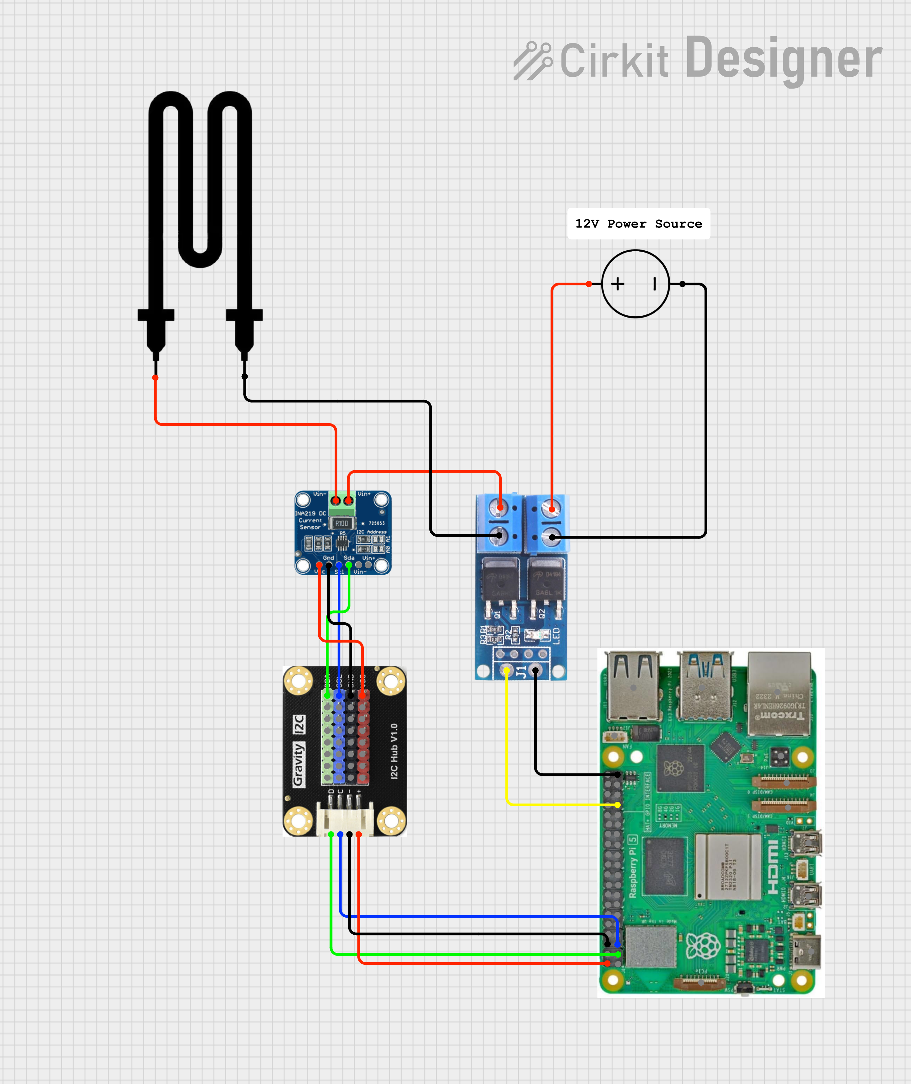
Example using an ina219 to measure dew heater voltage and current
Available in
-
Daytime
- The Day time pipeline
-
Nighttime
- The Night time pipeline
-
Periodic
- The Periodic pipeline